Embedded programming
This week’s group assignment is to Compare the performance and development workflows for other architectures. For this assignment we experimented with programming several micxrocontroller boards.
Arduino 101
For the group assignment I chose to try working on Arduino 101. At first I read about it in First steps with Arduino 101 & Arduino 101 guide
Performance & Architecture
Arduino 101 combine the ease-of-use of the classic boards with the latest technologies.
The board recognises gestures, and features a six-axis accelerometer and gyroscope.
A learning and development board that delivers the performance and low-power consumption
of the Intel® Curie™ Module with the simplicity of Arduino at an entry-level price.
It keeps the same robust form factor and peripheral list of the UNO with the addition of
onboard Bluetooth LE capabilities and
a 6-axis accelerometer/gyro to help you easily expand your creativity into the connected world.
The module contains two tiny cores, an x86 (Quark) and a 32-bit ARC architecture core, both
clocked at 32MHz. The Intel toolchain compiles your Arduino sketches optimally across both
cores to accomplish the most demanding tasks.
The Real-Time Operating Systems (RTOS) and framework developed by Intel is open sourced.
The Arduino core communicates with the RTOS via static mailboxes to accomplish a predefined list of tasks (interface with PC using USB, program the sketch into flash, expose Bluetooth LE functionality to sketch, perform PWM).
The 101 comes with 14 digital input/output pins (of which 4 can be used as PWM outputs),
6 analog inputs, a USB connector for serial communication and sketch upload, a power jack,
an ICSP header with SPI signals and I2C dedicated pins. The board operating voltage and I/O
is 3.3V but all pins are protected against 5V overvoltage.
The Arduino 101 and the Genuino 101 boards have been designed in collaboration with Intel®.
Specicications:
-
Microcontroller: Intel Curie
-
Operating Voltage: 3.3V (5V tolerant I/O)
-
Input Voltage (recommended): 7-12V
-
Input Voltage (limit): 7-17V
-
Digital I/O Pins: 14 (of which 4 provide PWM output)
-
PWM Digital I/O Pins: 4
-
Analog Input Pins: 6
-
DC Current per I/O Pin: 20 mA
-
Flash Memory: 196 kB
-
SRAM: 24 kB
-
Clock Speed: 32MHz
-
LED_BUILTIN: 13
-
Features: Bluetooth LE, 6-axis accelerometer/gyro
Programming
I downloaded Arduino IDE from this link
Then, I added the Intel Curie Core to it. Selectd board type and port from Tools select the Board Arduino/Genuinio 101 and then the Port that is labeled with the same name.
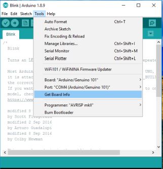
Went to File on the Arduino Software (IDE) and opened the Examples tree; selected 01. Basic and then Blink
Uploading the code to the board can be done by pressing the second round icon from left on the top bar of the Arduino Software (IDE) or press Ctrl+U or select the menu Sketch and then Upload.
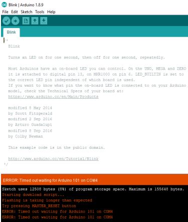
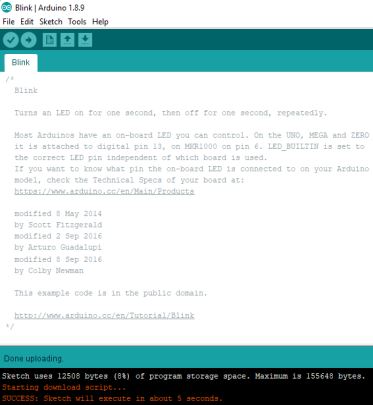
Got an error at first, so I tried the IDE suggestion to click on Master reset button.
Blink code
// the setup function runs once when you press reset or power the board
void setup() {
  // initialize digital pin LED_BUILTIN as an output.
  pinMode(LED_BUILTIN, OUTPUT);
}

// the loop function runs over and over again forever
void loop() {
  digitalWrite(LED_BUILTIN, HIGH);   // turn the LED on (HIGH is the voltage level)
  delay(1000);                       // wait for a second
  digitalWrite(LED_BUILTIN, LOW);    // turn the LED off by making the voltage LOW
  delay(1000);                       // wait for a second
}
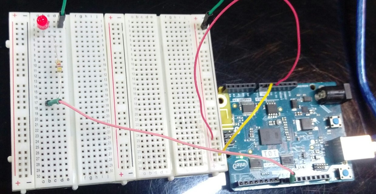
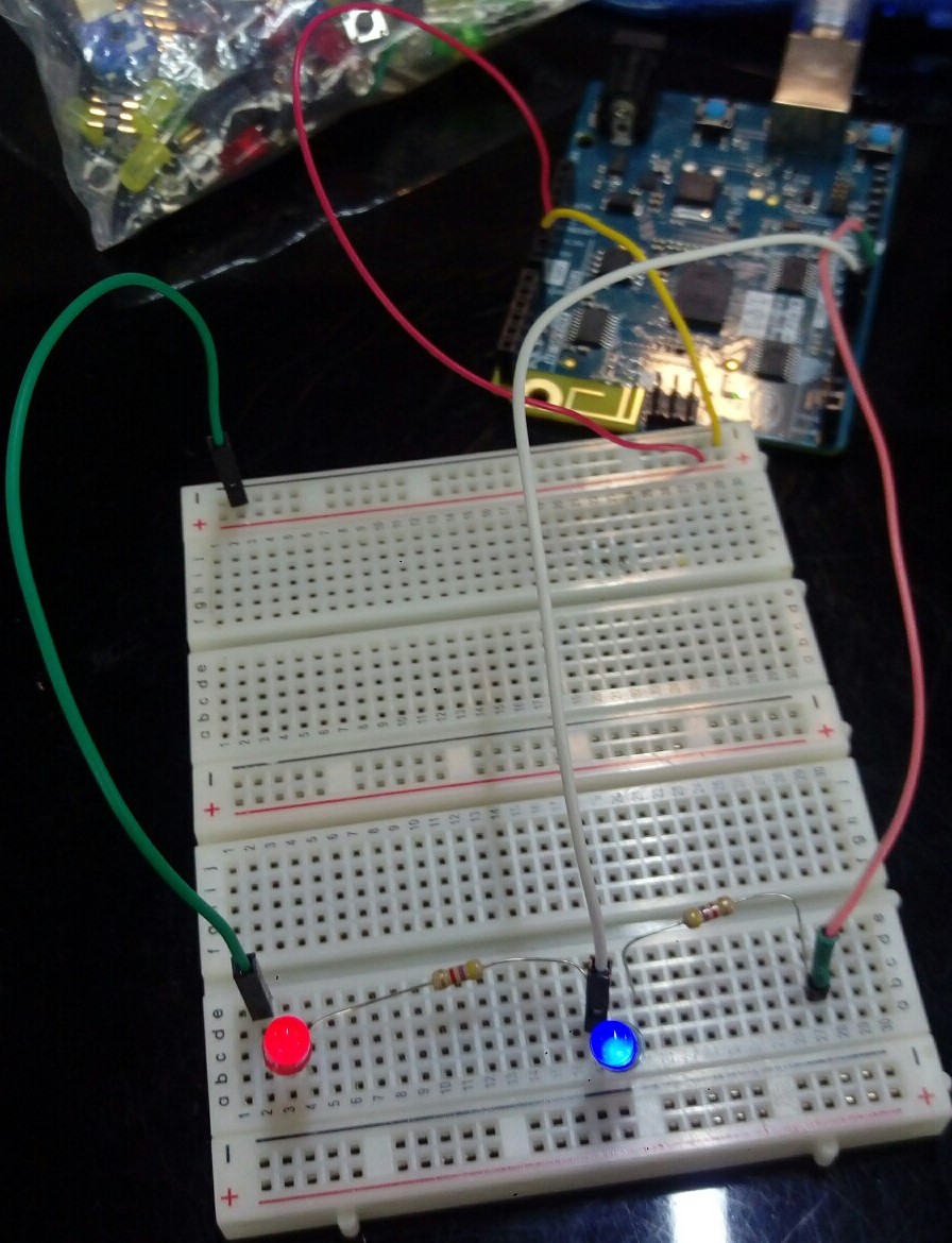
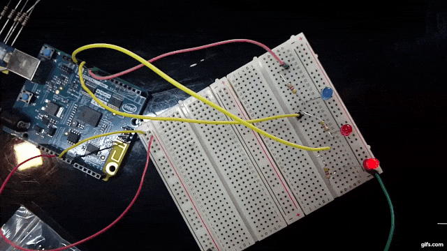
Then, I tried the Fade code, but I needed to connect the Arduino board to breadboard. At first, it didn’t work because I didn’t connect the board in the right way but when I modified them, it worked.
Then I tried an example to fade an LED
/*
  Fade

  This example shows how to fade an LED on pin 9 using the analogWrite()
  function.

  This example code is in the public domain.

  http://www.arduino.cc/en/Tutorial/Fade
*/

int led = 9;           // the PWM pin the LED is attached to
int brightness = 0;    // how bright the LED is
int fadeAmount = 5;    // how many points to fade the LED by

// the setup routine runs once when you press reset:
void setup() {
  // declare pin 9 to be an output:
  pinMode(led, OUTPUT);
}

// the loop routine runs over and over again forever:
void loop() {
  // set the brightness of pin 9:
  analogWrite(led, brightness);

  // change the brightness for next time through the loop:
  brightness = brightness + fadeAmount;

  // reverse the direction of the fading at the ends of the fade:
  if (brightness <= 0 || brightness >= 255) {
    fadeAmount = -fadeAmount;
  }
  // wait for 30 milliseconds to see the dimming effect
  delay(30);
}
Then I tried to modify the code to use a different pin. I changed it to pin 5 & changed the connection to Arduino board & it worked.
int led = 5; // the PWM pin the LED is attached to
After that, I added one more LED & modified the code to make them fade at the same time. At first it didn’t work because of wrong connection but after doing some adjustment it worked.
int led = 9;           // the PWM pin the LED is attached to
int led2 = 6;           // the PWM pin the LED2 is attached to
int brightness = 0;    // how bright the LED is
int fadeAmount = 5;    // how many points to fade the LED by

// the setup routine runs once when you press reset:
void setup() {
  // declare pin 9 & 6 to be an output:
  pinMode(led, OUTPUT);
  pinMode(led2, OUTPUT);
}

// the loop routine runs over and over again forever:
void loop() {
  // set the brightness of pin 9 & 6:
  analogWrite(led, brightness);
  analogWrite(led2, brightness);

  // change the brightness for next time through the loop:
  brightness = brightness + fadeAmount;

  // reverse the direction of the fading at the ends of the fade:
  if (brightness <= 0 || brightness >= 255) {
    fadeAmount = -fadeAmount;
  }
  // wait for 30 milliseconds to see the dimming effect
  delay(30);
}
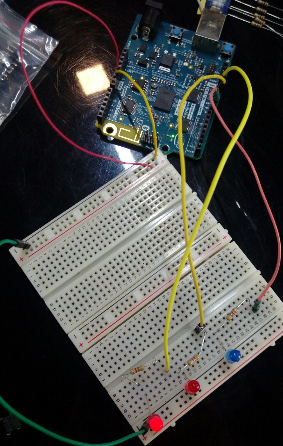
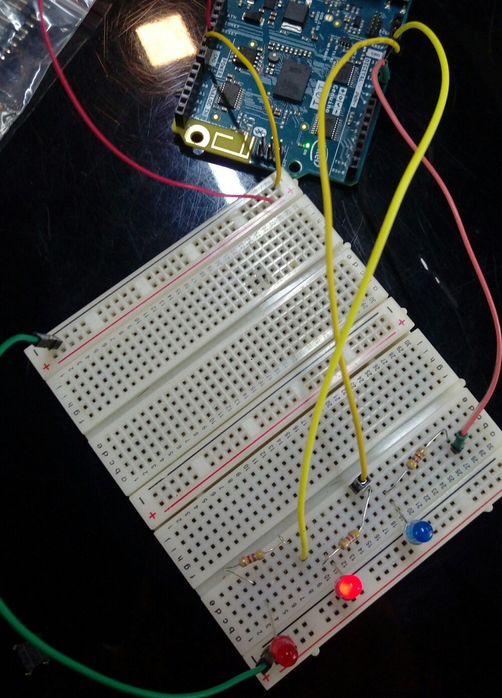
I tried to make LED sequencer by modifying this example
int led = 9;           // the PWM pin the LED is attached to
int led2 = 10;           // the PWM pin the LED2 is attached to
int led3 = 12;           // the PWM pin the LED2 is attached to
void setup() {
   // declare pin 9 & 6 to be an output:
  pinMode(led, OUTPUT);
  pinMode(led2, OUTPUT);
  pinMode(led3, OUTPUT);
}

void loop() {
digitalWrite(led, HIGH);
  digitalWrite(led2, LOW);
  digitalWrite(led3, LOW);
  delay(300);

  digitalWrite(led, LOW);
  digitalWrite(led2, HIGH);
  digitalWrite(led3, LOW);
  delay(300);

  digitalWrite(led, LOW);
  digitalWrite(led2, LOW);
  digitalWrite(led3, HIGH);
  delay(300);

}
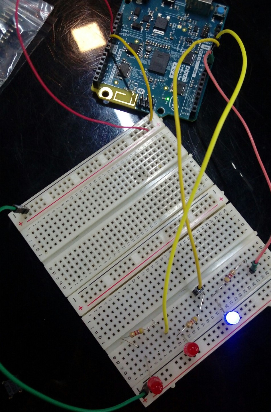
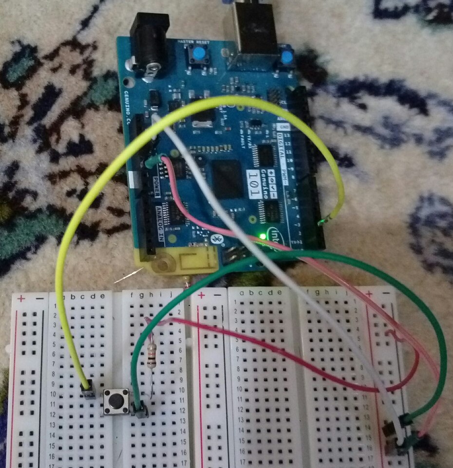
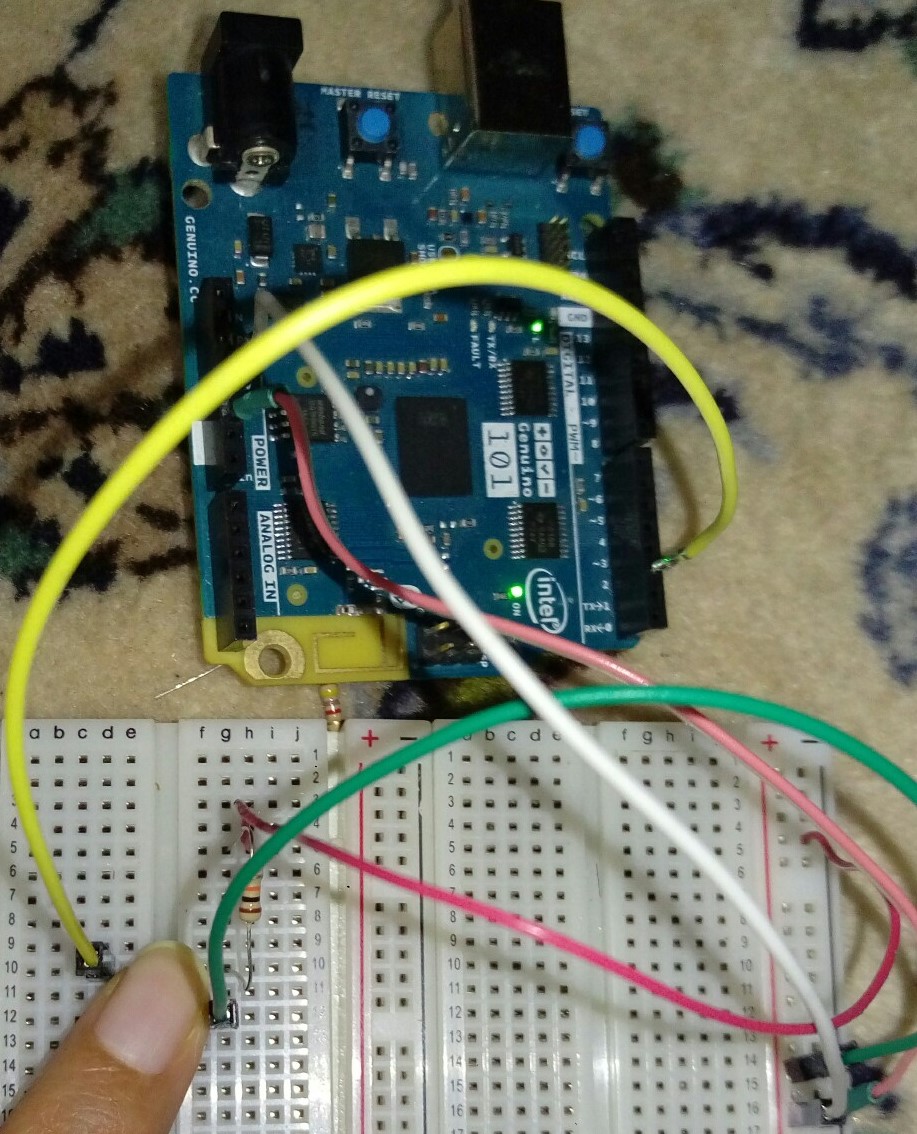
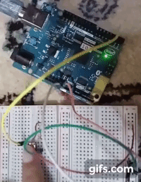
Then, tried to turns on the built-in LED when pressing the button.
/*
  Button

  Turns on and off a light emitting diode(LED) connected to digital pin 13,
  when pressing a pushbutton attached to pin 2.

  The circuit:
  - LED attached from pin 13 to ground
  - pushbutton attached to pin 2 from +5V
  - 10K resistor attached to pin 2 from ground

  - Note: on most Arduinos there is already an LED on the board
    attached to pin 13.

  created 2005
  by DojoDave <http://www.0j0.org>
  modified 30 Aug 2011
  by Tom Igoe

  This example code is in the public domain.

  http://www.arduino.cc/en/Tutorial/Button
*/

// constants won't change. They're used here to set pin numbers:
const int buttonPin = 2;     // the number of the pushbutton pin
const int ledPin =  13;      // the number of the LED pin

// variables will change:
int buttonState = 0;         // variable for reading the pushbutton status

void setup() {
  // initialize the LED pin as an output:
  pinMode(ledPin, OUTPUT);
  // initialize the pushbutton pin as an input:
  pinMode(buttonPin, INPUT);
}

void loop() {
  // read the state of the pushbutton value:
  buttonState = digitalRead(buttonPin);

  // check if the pushbutton is pressed. If it is, the buttonState is HIGH:
  if (buttonState == HIGH) {
    // turn LED on:
    digitalWrite(ledPin, HIGH);
  } else {
    // turn LED off:
    digitalWrite(ledPin, LOW);
  }
}
Modified the code a bit to make the LED flashes twice when the button is pressed
const int buttonPin = 2;     // the number of the pushbutton pin
const int ledPin =  13;      // the number of the LED pin

// variables will change:
int buttonState = 0;         // variable for reading the pushbutton status

void setup() {
  // initialize the LED pin as an output:
  pinMode(ledPin, OUTPUT);
  // initialize the pushbutton pin as an input:
  pinMode(buttonPin, INPUT);
}

void loop() {
  // read the state of the pushbutton value:
  buttonState = digitalRead(buttonPin);

  // check if the pushbutton is pressed. If it is, the buttonState is HIGH:
  if (buttonState == HIGH) {
    // LED flashes:
    digitalWrite(ledPin, HIGH);
    delay(200);
    digitalWrite(ledPin, LOW);
    delay(200);
    digitalWrite(ledPin, HIGH);
    delay(200);


  } else {
    // turn LED off:
    digitalWrite(ledPin, LOW);
  }
}
Circuit playground express
For this assignment, I have chosen to program the Adafruit Circuit Playground Express. Before starting, I looked up the playground circuit online to read about it since I am not aware of what it does and what to do with it. I read about it from the Adafruit website itself, Adafruit Circuit Playground Express Overview.
Then, from the website I started exploring the tutorials and the different methods of programming it. Initially, since I do not have plenty of background in electronics, I used the MakeCode that adafruit provides for programming the circuit playground. Microsoft MakeCode for Adafruit is a web-based code editor for physical computing. It provides a block editor, similar to Scratch or Code.org, and also a JavaScript editor for more advanced users.
This was an easy way to start programming. Just by editing the blocks, the simulator will automatically restart and run the code.
After getting along with the board, I tried using Arduino IDE to program it. I used the hello temperature example from the adafruit playground circuit example.
In the tutorials that adafruit has, I did two examples, siren and clapping hands. I just follwed the tutorial steps shown and programmed it.
MakeCode
Siren example
This example will have the police lights show along the with sound of the police siren.
The image below will show the blocks for programming it and a video of the output.
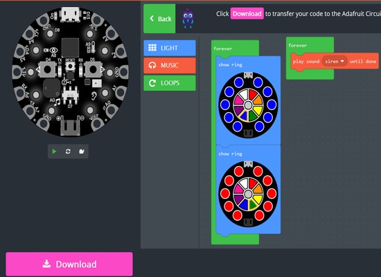
The circuit board on the left of the image also shows the preview of the output. You can test if your circuit will run just by clicking on the play button.
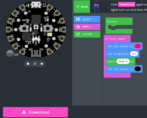
Clapping hands example
This example will have the lights turn on the moment you clap your hands. The lights will stay lit for 2 seconds and then turn off.
The image below will show the blocks for programming it and a video of the output.
Arduino IDE
Hello_Temperature example
Before starting to program using the arduino software, I had to read everything about how to program it in the adafruit website. I followed the steps to set up the playground circuit in their website itself.
The first thing I had to do is to
-
Install the ‘Arduino SAMD boards’ in the version 1.6.16 or later from the Tools>Board>Board manager menue.
-
Type ‘Arduino SAMD’ in the top search bar, then when you see the entry, click Install.
-
Quit and reopen the Arduino IDE just to ensure that all of the boards are properly installed. You should now be able to select and upload to the new boards listed in the Tools->Board menu.
-
Go to Tools>Board and select ‘Adafruit Circuit PLayground Express’.
-
Before starting to program the board, you will possibly need to install a driver. I installed the driver from the same page I mentioned earlier to follow the steps. Download and run the installer and then you can start programming.
In arduino, I wanted to try something different other than the lights. I went and searched the examples that comes with the circuit itself. I typed in the adafruit website ‘Hello Temperature’ example for the circuit and there was a tutorial of how to do it. Again, I just followed the steps and programmed the circuit. Here is a link to the tutorial page.
I just went to File>Examples>Adafruit Circuit Playground>Hello_ CircuitPlayground>Hello_Temperature, and directly uploaded the sketch.
This was the code example I used for programming.
#include <Adafruit_CircuitPlayground.h>


float tempC, tempF;


void setup() {

  Serial.begin(9600);

  CircuitPlayground.begin();

}


void loop() {

  tempC = CircuitPlayground.temperature();

  tempF = CircuitPlayground.temperatureF();


  Serial.print("tempC: ");

  Serial.print(tempC);

  Serial.print("  tempF: ");

  Serial.println(tempF);


  delay(1000);

}
This sketch will give me the surrounding temperature in which the temperature sensor on the circuit board will detect. The temperature will be displayed for an interval of one second.
With the sketch loaded and running on the circuit playground, I opened the serial monitor from Tools>Serial Monitor to display the temperature every one second. I then placed my finger on top of the sensor to check whether the sensor will be able to detect the temperature increase. The video below will show the results.
I closed the serial monitor and opened the serial plotter from Tools>Serial Plotter. This will show the same result except that here the temperatures will be shown in a graphical representation.
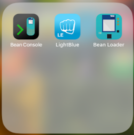
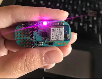
Lightblue Bean
For the lightblue bean i have used three apps on my phone to program it:
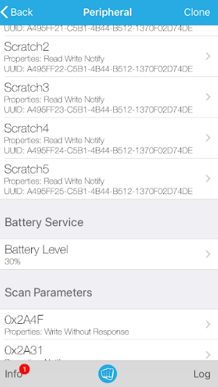
In the lightblue app
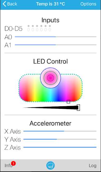
It is an interesting app as it allows you to adjust the rgb color
Also it shows you the position of the accelerometer. Moreover, it can tell you the battery level
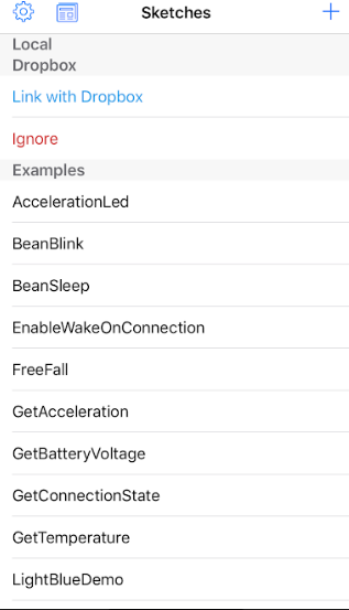
The second app is the bean loader
In this app you can program the bean
There are multiple ready codes available on the app and it allows you to try them out.
As a start I have tried to test the bean blink code:
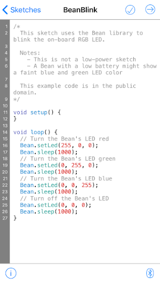
Then I have sent the code to the bean by clicking on the arrow
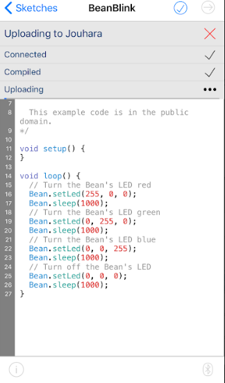
And the bean started blinking
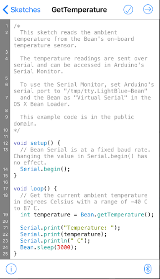
Then I tried to test the get temperature code
And to check the data I have referred to the bean console app
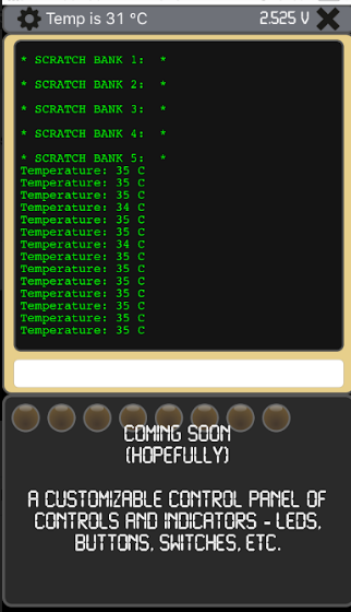
And it was receiving feedback from the chip every milliseconds
feather nrf52 bluefruit
We have started this week by working on the group assignment. There were many of microcontrollers/development boards available in the lab. To test as many as we can, each student has taken a specific circuit to work with. For me, I chose to work on Bluefruit nRF52832 Feather. This is because I have not worked with this module before, so learning about it throught this assignment will be a great outcome.
To get started with the module, I have visited the adafruit site. Through the site, I learned what this chip is, it features, pins and assembly methods. Then, to set-up and test the board, I have followed the instructions that are written in the site as well. Firstly, for the setup, I have installed the board support package in the Arduino IDE following these steps:
1- I deleted the old version of the Arduino IDE installed in my laptop and I downloaded the new one ARDUINO 1.8.9.
2- Next, I opened the IDE and added the Adafruit nRF52 package.
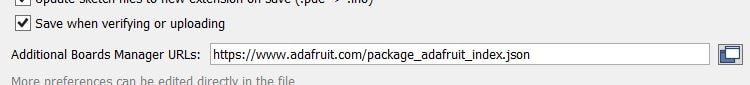
3- By clicking on the File > Preferences. This window will appear.

4- In the Additional Board Manager URL section I added this linked “https://www.adafruit.com/package_adafruit_index.json”.
5- Finally, from Tools > board > board manager, I installed the “Adafruit nRF52 by Adafruit”.
.jpg)
Moving to the next part which is testing, I tried to blink the LED that is located next to the USB port. This was a simple test just to check that my board is working. Here are th steps:
1- I plugged the board into my PC through the USB port.
.jpg)
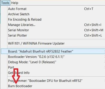
2- From Tools > Boards, I chose my board to be “Adafruit Bluefruit nRF52832 Feather”.

3- I have updated the bootloader by clicking on the Tools > Burn Bootloader.
4- Then, port COM9 selected.
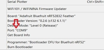
5- The Bootloader updated again.
6- Finally, I uploaded this code and the LED start blinking.
void setup() {
  pinMode(LED_BUILTIN, OUTPUT);
}

void loop() {
  digitalWrite(LED_BUILTIN, HIGH);   // turn the LED on (HIGH is the voltage level)
  delay(1000);                       // wait for a second
  digitalWrite(LED_BUILTIN, LOW);    // turn the LED off by making the voltage LOW
  delay(1000);                       // wait for a second
}
To examine the functionalities of the board even further, I did another test called BLE UART: Controller Example. In this test I have used Bluefruit LE app to send some data to my nRF52 module. The example and the details of it also available in adafruit site. by following the instructions in the site I succeed in transferring data and here are the steps:
1- I downloaded the Adafruit Bluefruit LE Connect app in my phone.

2- I uploaded the controller example sketch in the Arduino IDE.
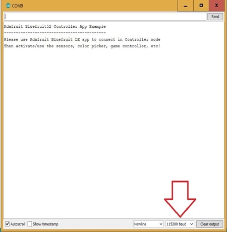
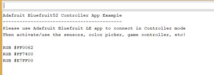
3- I opened the serial monitor by clicking on the following icon.

4- I changed the baud to 115200 to match what is written in the program (code).
5- Return back to the app, I connected it to the target “Bluefruit52”.
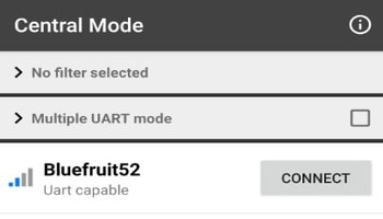
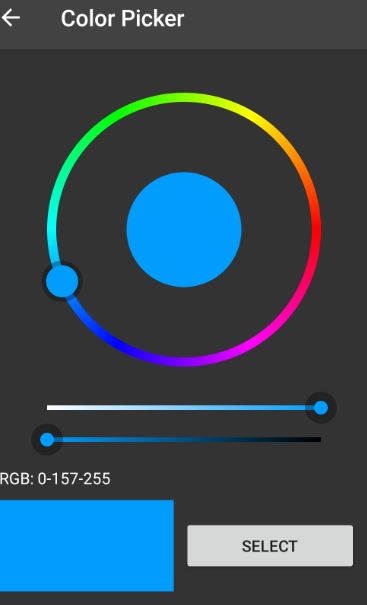
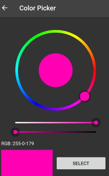
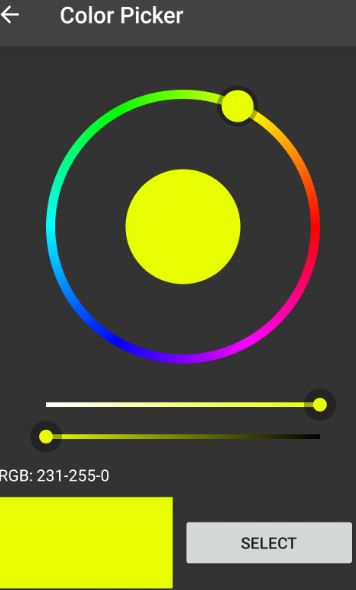
6- Then, I clicked on the controller > color picker.

7- I was choosing different colors, selected them, then the codes of those colors were appearing in the serial monitor of the Arduino IDE.
Metamotion R
I started with the “MetaMotionR” its a chip the has alot of sensors such as pressure, temprature and accelerometer. It is connected to the phone through buletooth and controlled by an app.

This is how you Setup your board.
You can choose in the app the parameter you need then the chip will send you the data as Excel sheet.


Curienano
Then I worked on “curienano board” which is a smaller version of the arduino 101.

Following these tutorials 1 and 2 that showed how we can use the arduino ide with scrach for arduino “S4A” to control the board LED using the labtop arrow keys.
