Electronics production
This week’s group assignment is to Characterize the design rules for the PCB production process
Fab Modules
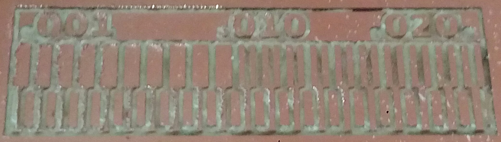
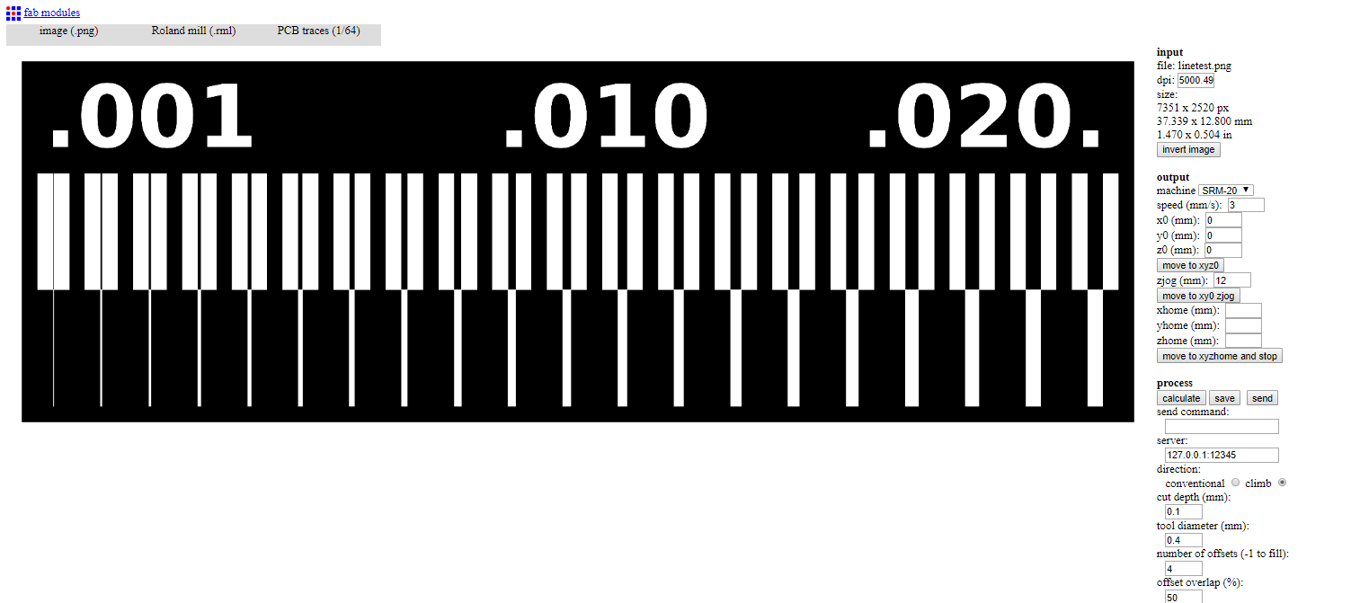
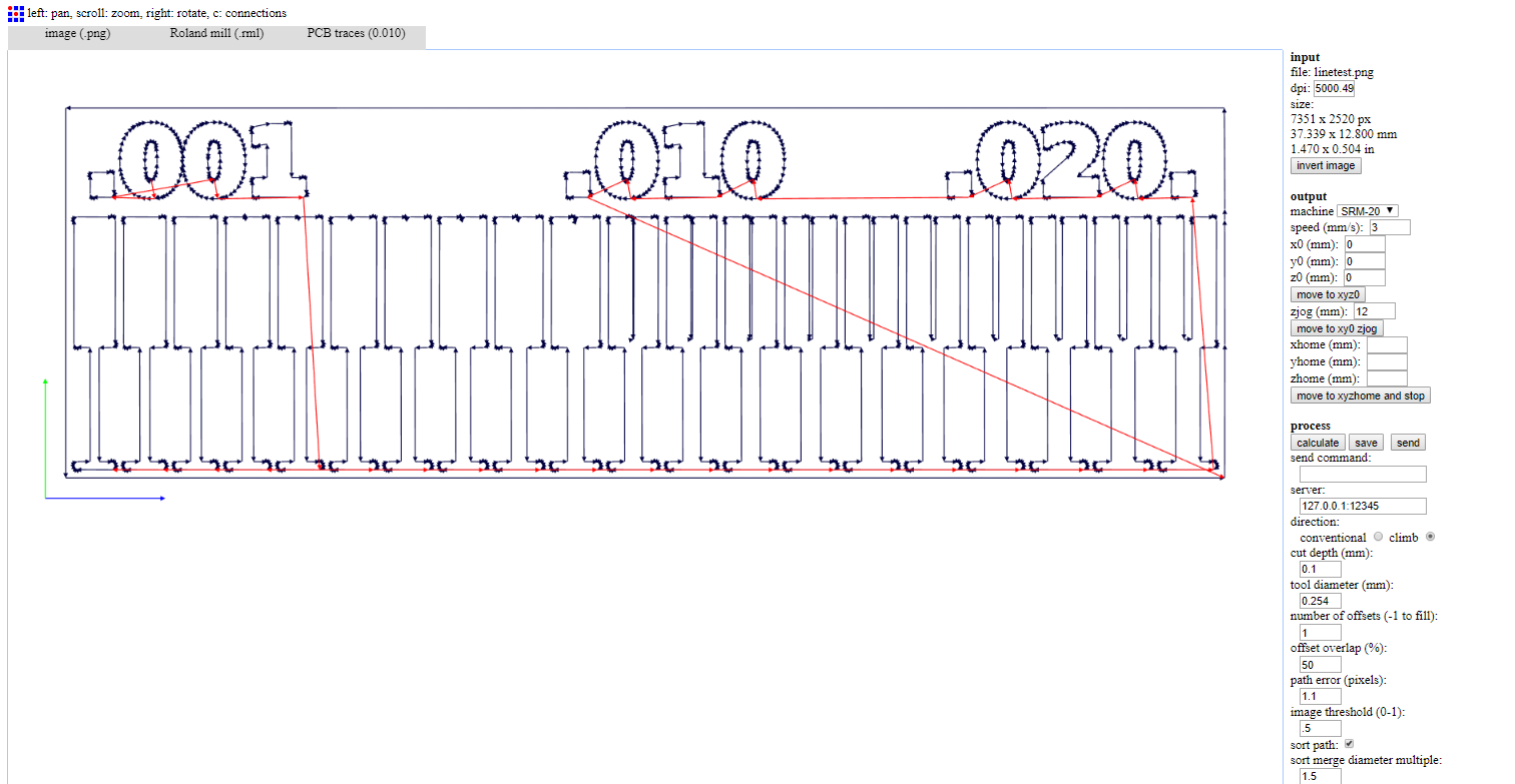
We have used Roland Modela (SRM-20) for this week assignment. We opened the image for testing in Fab Modules and went through the steps in this Tutorial.
Steps:
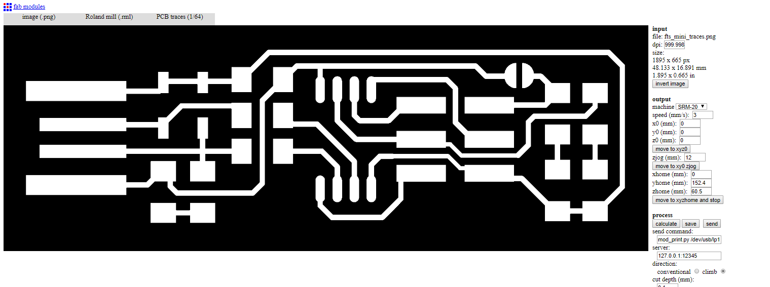
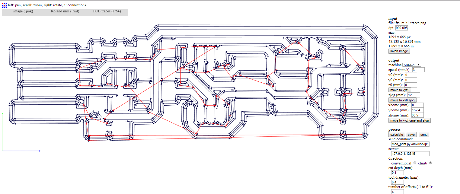
- Input format - PNG - select your traces image
- Output format - roland mill (.rml)
- Process - PCB traces (1/64)
The settings on the right side:
- Machine - SRM-20
- x0(mm) - 0
- y0(mm) - 0
- z0(mm) - 0
- zjopg - 12
- Speed - 4 or 3 mm/s for new end mills
Click “calculate”
Then “save”
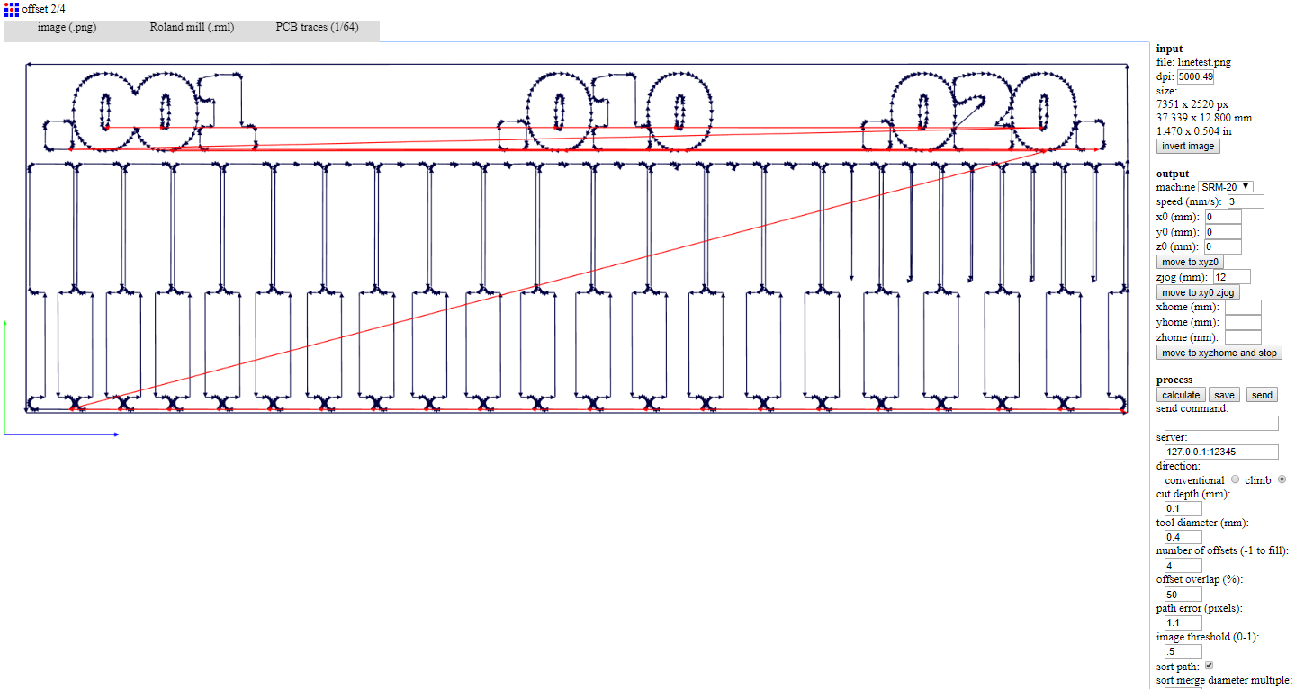
We tried to do calculate with diffrent bit sizes to see the difference
We followed the same steps to make our PCBs.
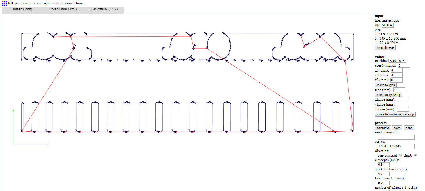
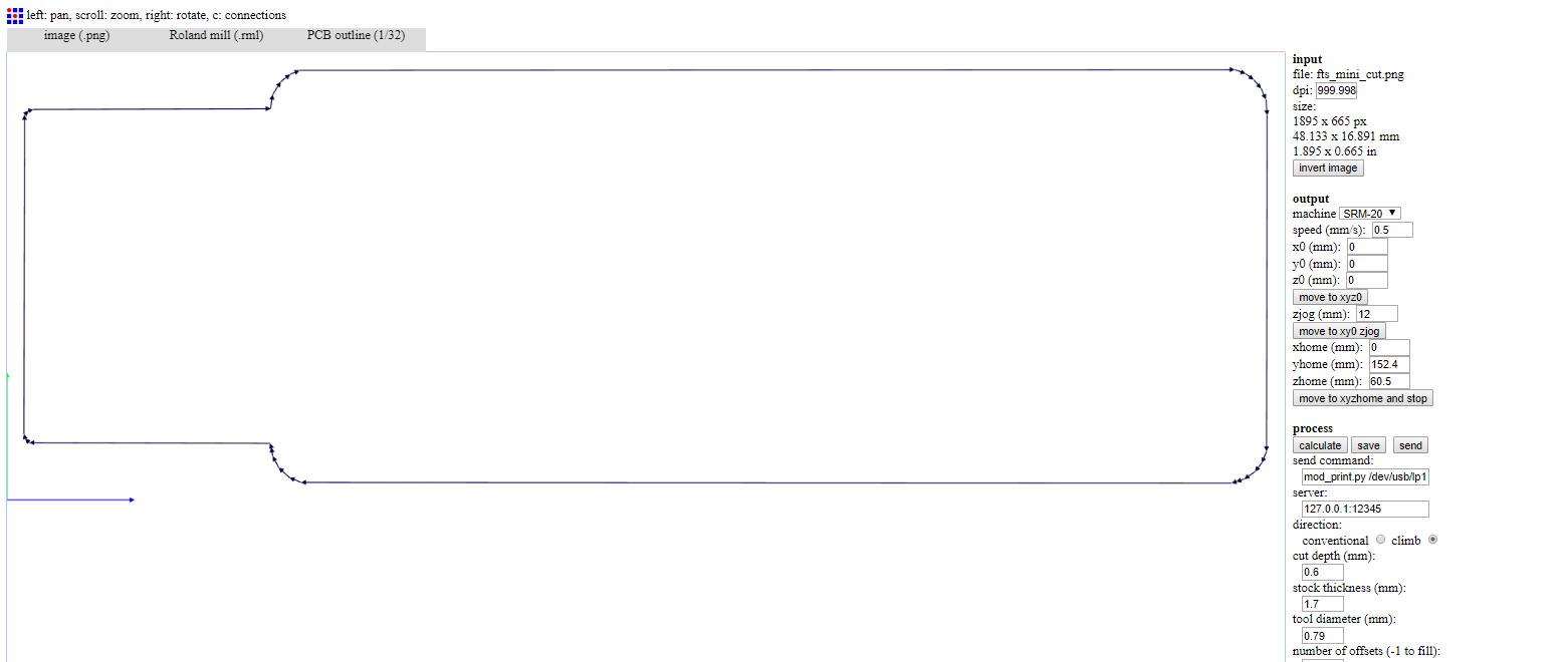
& these are the steps for the outline
- input format - PNG - select your traces image
- output format - roland mill (.rml)
- process - PCB outline (1/32)
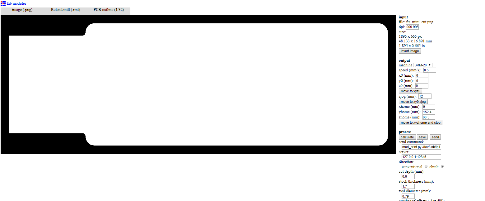
Settings:
- Machine - SRM-20
- x0(mm) - 0
- y0(mm) - 0
- z0(mm) - 0
- zjopg - 12
- Speed - 0.5
Then clicking “calculate” & “save”
We followed the same steps to make our PCBs.
Using VPanel
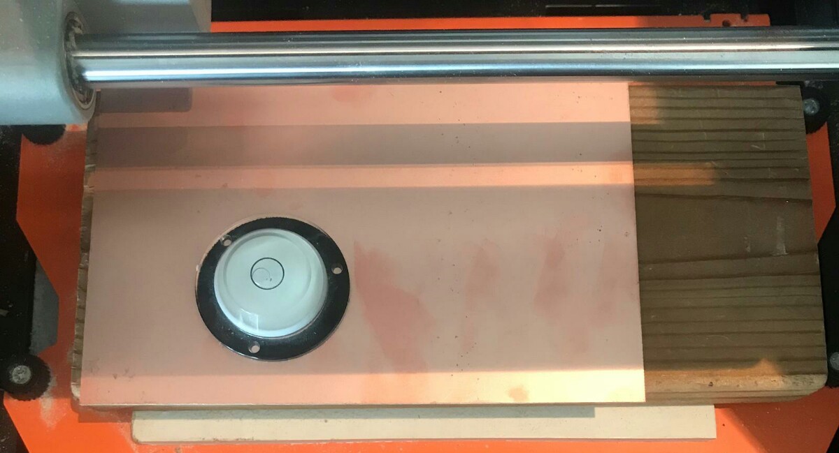
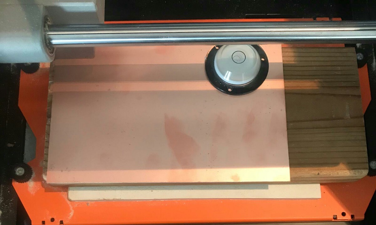
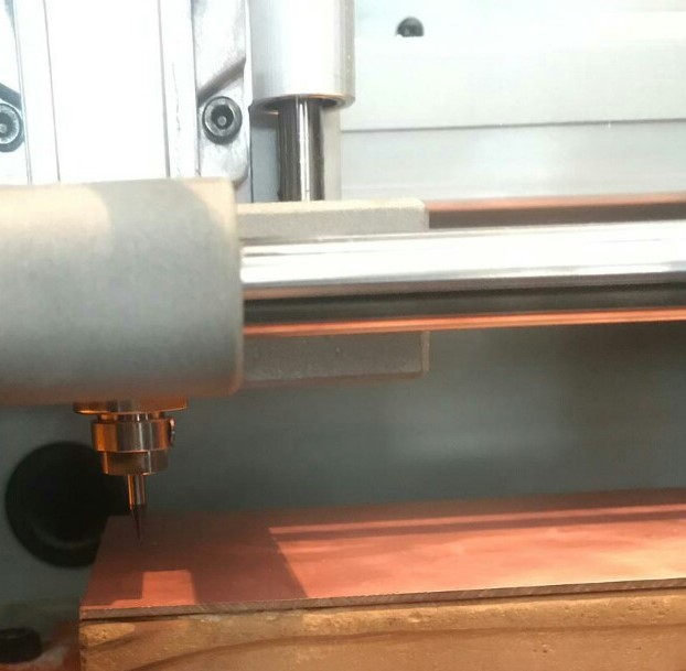
There is be a piece of wood taped down on the machine securely. We applied double sided tape & placed and pressed the board down on the sacrificial board securely.
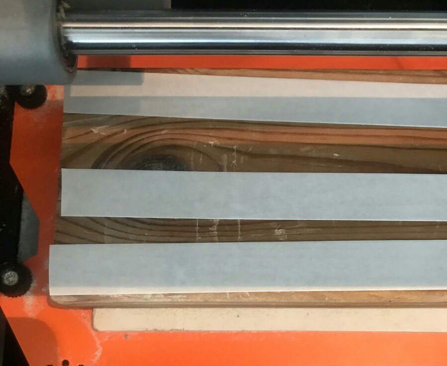
Then, we used a leveler in all corners to make sure that the PCB is leveled.
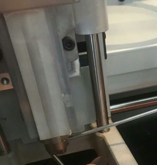
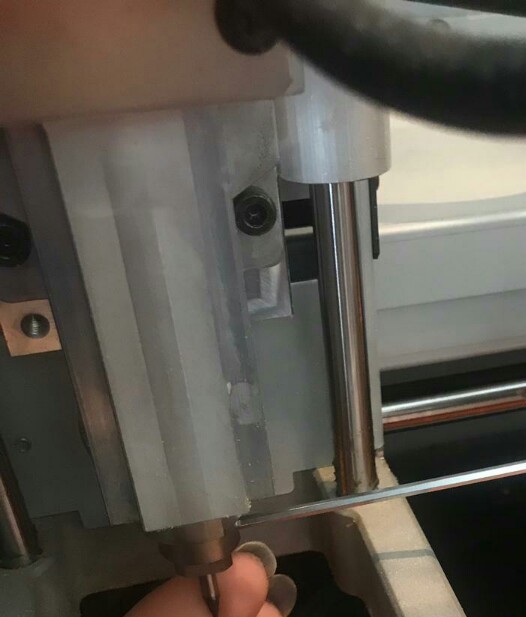
We turned on Roland Modela and opened VPanel for SRM-20. We inserted a new milling tip to the machine and we screwed it. Then, we warmed the spindle for 5 min at mid Rpm before using it.
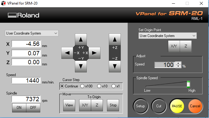
We adjusted the X/Y origin point by moving the tip using the arrows and saved the origin. We adjusted the Z origin by moving the tip down untill it almost touched the surface of the PCB then we released the screw of the tip to let it touch the surface and we pressed the PCB board slightly down then we tightned it again and saved the origin.
We clicked “Cut” on the control panel. A new window appeared we selected the traces cutting file, then clicked Output and the machine started.
We cleaned the board and replaced the bit to 1/32 to do the outcut. After zeroing the Z (only the Z) we clicked “CUT” in the control panel and we choose the outcut (outline) file and clicked Output.