3D Scanning and printing
This week’s group assignment is to Test the design rules for the 3D printer
Our Own Design Test
For this weeks design, we had to first test our printer by designing different curves, inclinations, thicknesses, diameters etc, to check how accurate the printer prints. This should be done before printing our own models.
Instead of doing a normal 3D printing test, our instructor thought of an inspiration from a cathedral in which we can incorporate all the different factors required to test the 3D printer. Several images were looked at through google images in order to get an idea of how to create the testing model including all the factors, in addition to it being an additive model. While designing, each of us had different tasks to do such as searching for printing design rules, factors to consider for our model, different cathedral designs etc. Me and my other colleague were responsible of creating the model using solidworks. We were looking at different websites for 3D printing test rules until we came across Ultimaker’s, Designing for printability test. This website showed all the constraints that are to be considered before designing your model.
We created the design using solidworks and saved it as .stl file, and then uploaded it on sketchfab since we cannot upload solidworks files directly to sketchfab. Below will be the steps of how we created the model and the final cathedral design.
-
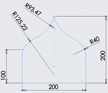
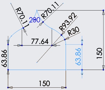
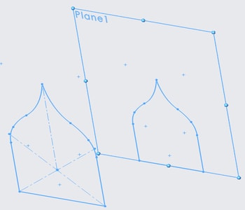
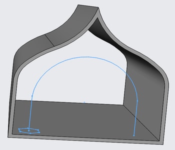
The first step was to sketch the outline of how we want the cathedral to look. We wanted to do a perspective view, therefore, we drew two sketches of the same outline, but scaled down the other one. Then, we used the loft feature to create the 3d model.

-
We used the shell and cut extrude feature to hollow out the model.

-
We used the sweep feature to create the arched columns. I defined the profile of the column and the guide of how I want it to look.

-
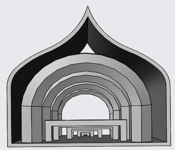
We then repeated the same procedure for the rest of the columns, except, we reduced their sizes and inclination.

-
We did the chairs using boss extrude feature.

-
Repeated the same procedure for the rest, except that we reduced their length.
-
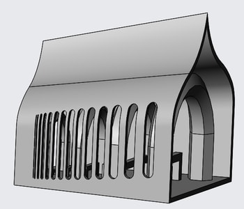
We did the cut outs using cut extrude feature.
-
We used the text tool for typing the text and engraved it using cut extrude feature.
-
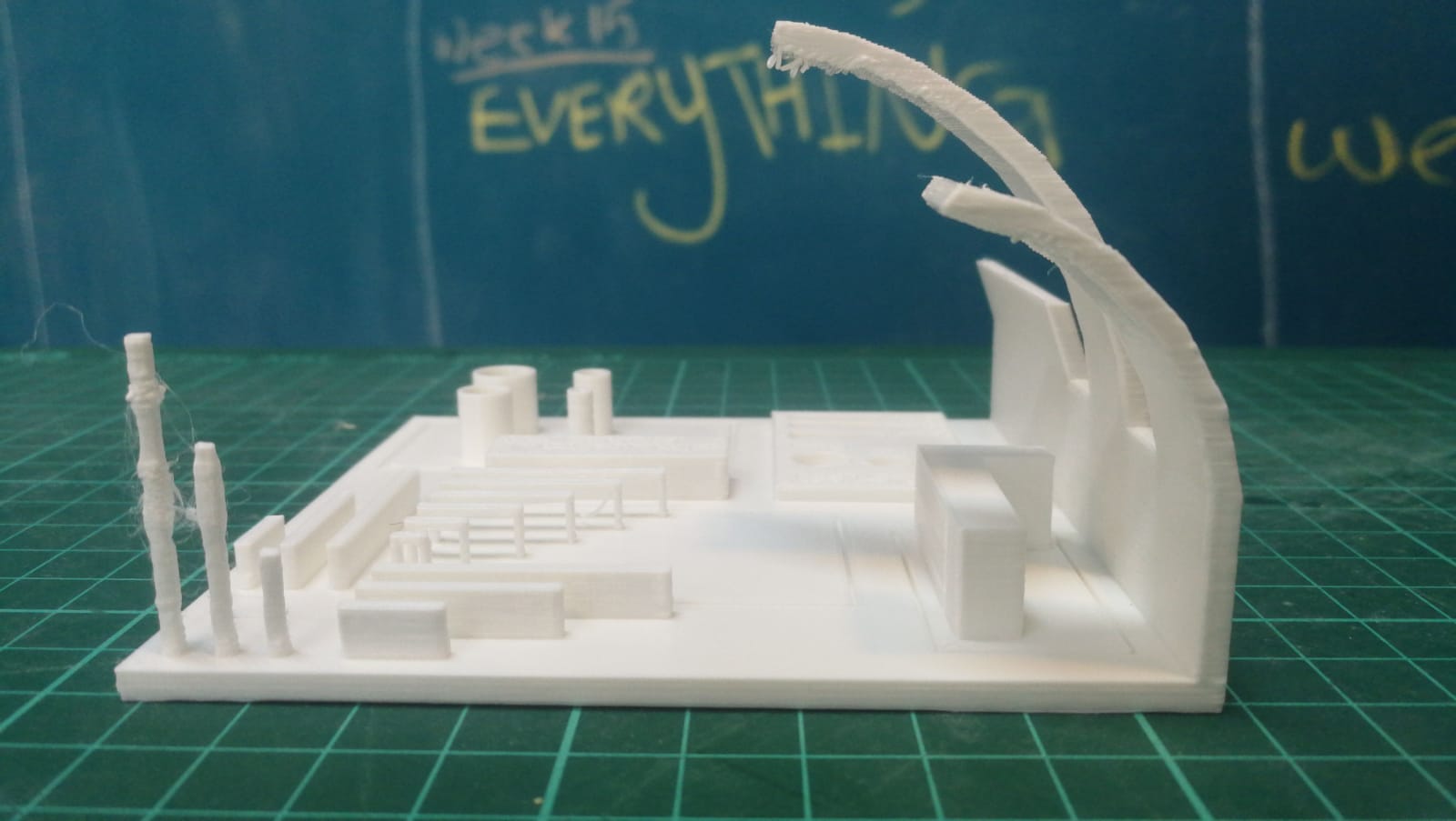
Lastly, we sketched the peak and used the boss extrude feature and the draft inwards option to create the peak.
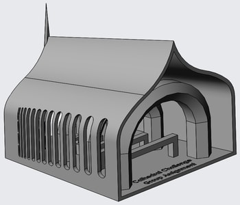
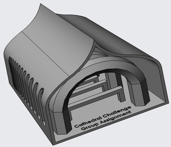
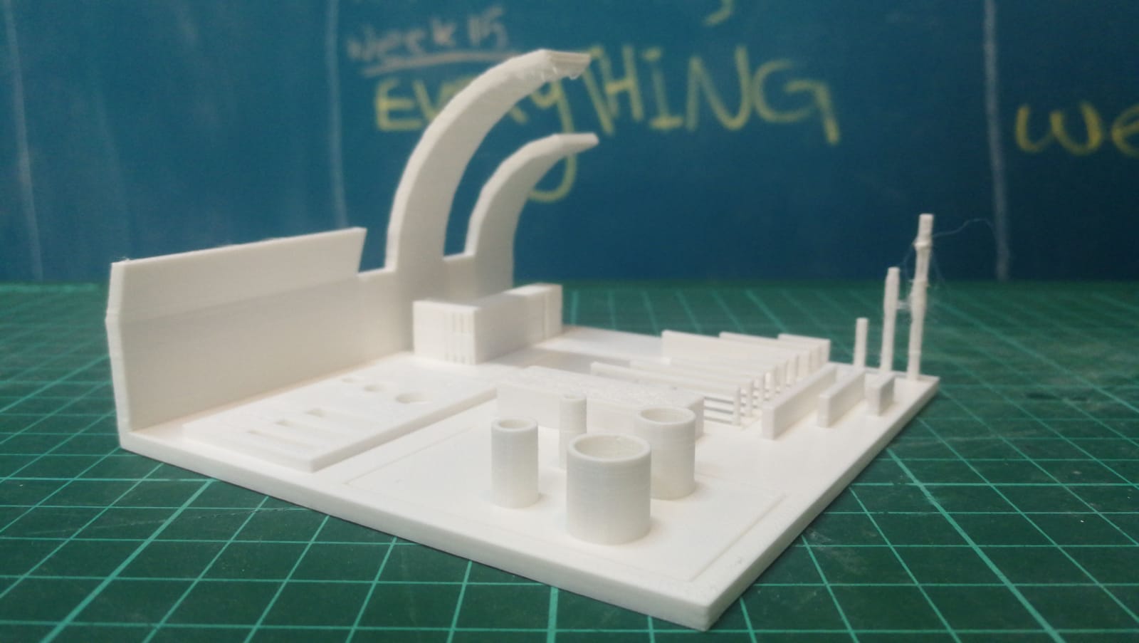
The design included:
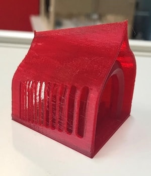
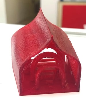
- Angles/Inclination testing which was created as the half shaped onion dome and the arched columns. The angles of the arches decreased as they get further into the cathedral, and this was to test how much further of an angle we can print without using support.
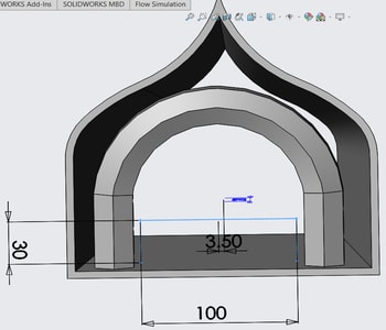
- Horizontal bridges as the seating arrangement of the cathedral. The bridges decreased in size starting from 100 mm to 10 mm. This is to test how much far the printer can travel horizontally wiithout causing any overhang.
- Wall thickness as the windows of the cathedral to test the line width and how thin it will be able to print.
- Engraving to test how clear the small details will show.
Below shows the printing settings used together with the final outcome.
Click here to download the solidworks file. Download file
Test 2
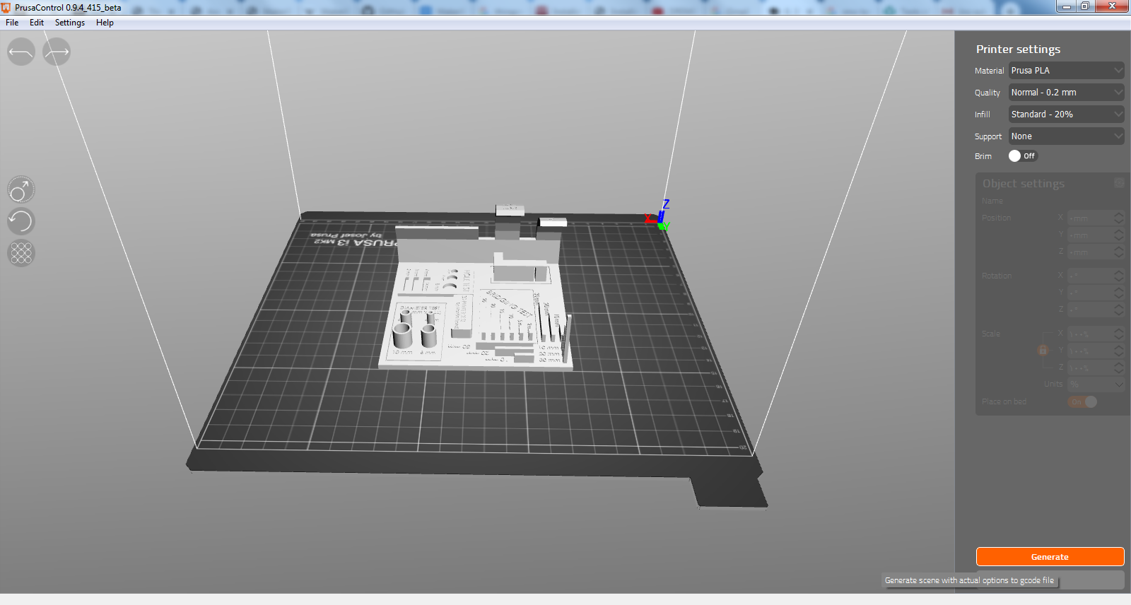
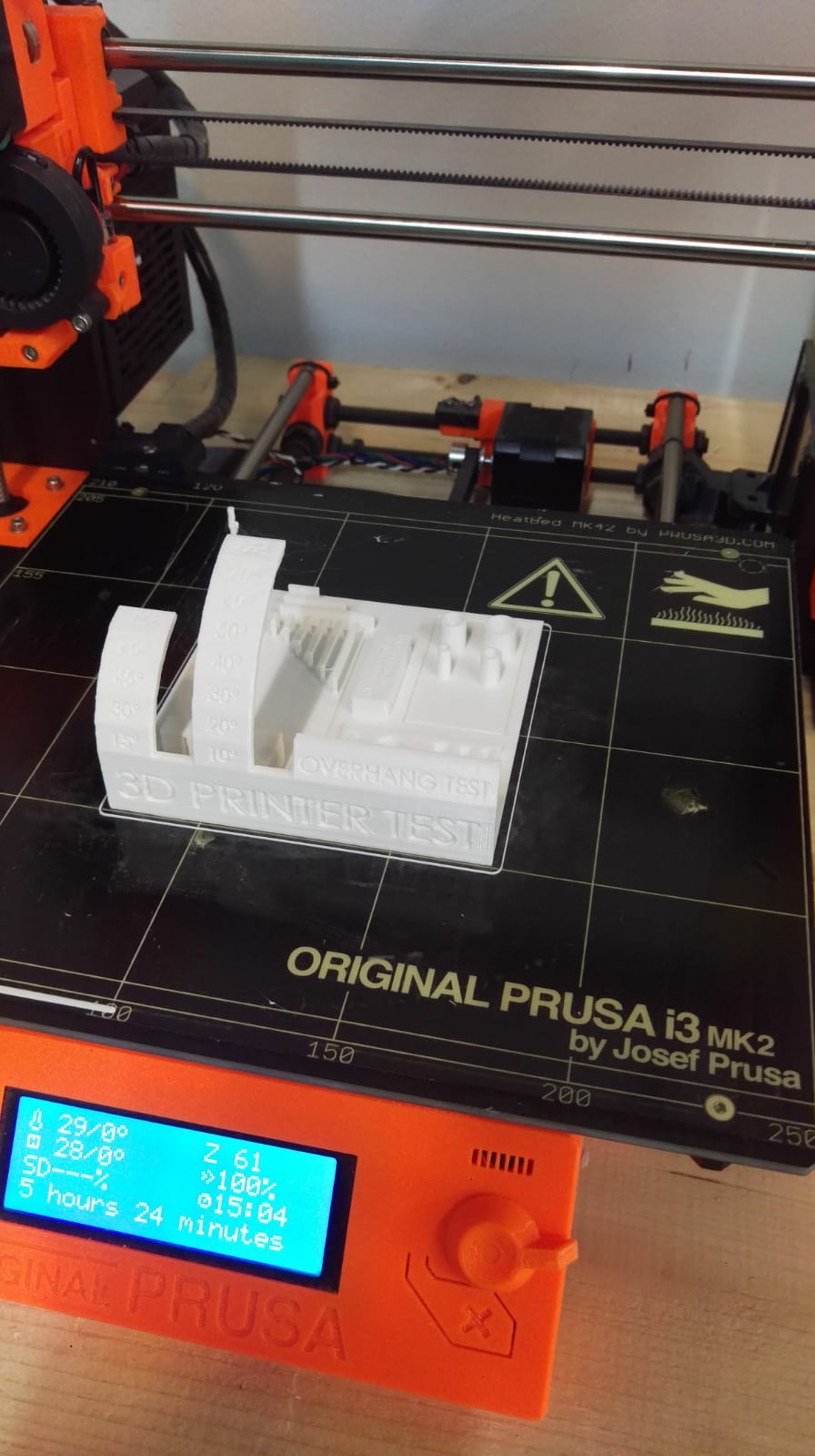
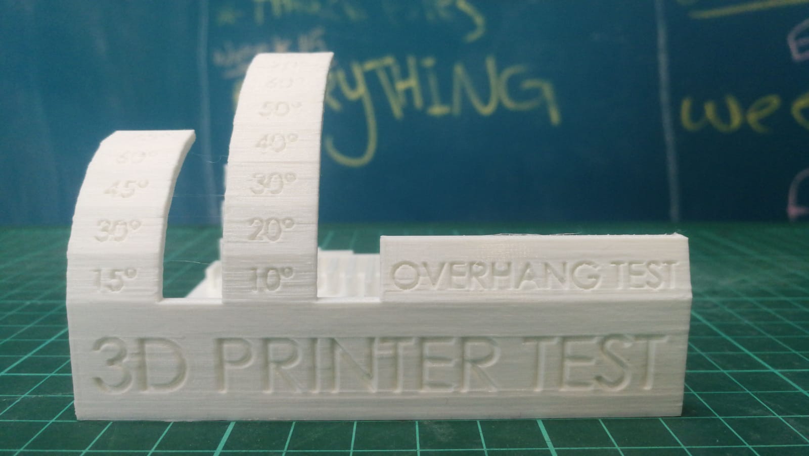
In addition to our own test we printed another ready test from this site
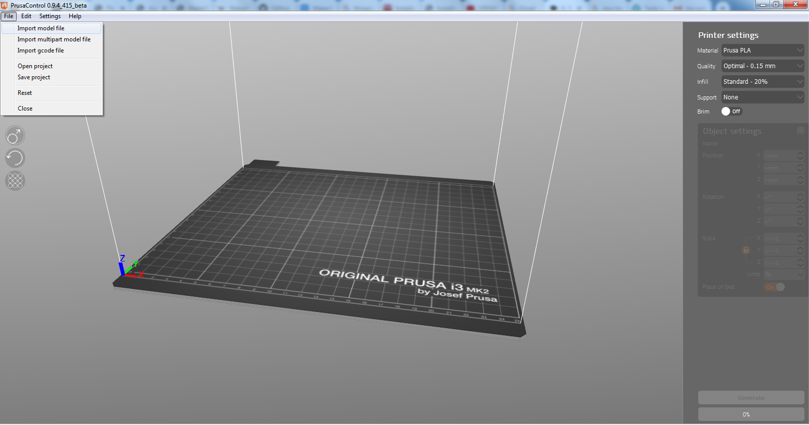
First we imported the file to the prusa controll software
Then click on generate to generate the g code that the printer understand
Then we saved the generated file to an SD card to plug it then to the printer
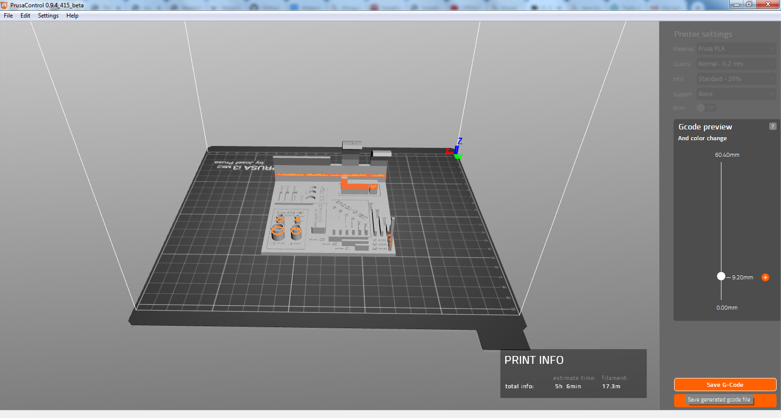
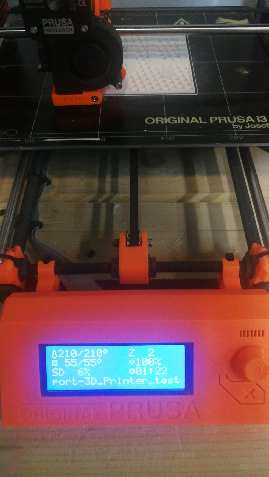
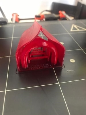
After 3:30 hour the object was ready
Problems
When we made the first print we had a curve this was beacuse the heat mat tempreture was not high enough so we increased the heat alittle bit the return it to the set point moreover we added a paper glue layer.
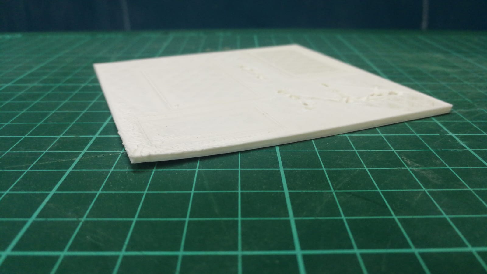
Our printed starting from 75 degree was not able to print correctly